Unlocking the Power of Motor Control Circuits

Ever wondered how machines spring to life with a flick of a switch? The magic lies within the intricate web of wires and components known as a motor control circuit. From the simplest household appliances to complex industrial robots, these circuits are the brains behind automated movement. Understanding the nuances of a motor control circuit wiring diagram is essential for anyone working with electrical systems.
Motor control circuits aren't just about turning motors on and off; they're about precision, efficiency, and safety. They regulate speed, direction, and torque, allowing machines to perform tasks with incredible accuracy. Think about the precise movements of a CNC machine or the smooth operation of an escalator – these are all thanks to meticulously designed motor control circuits.
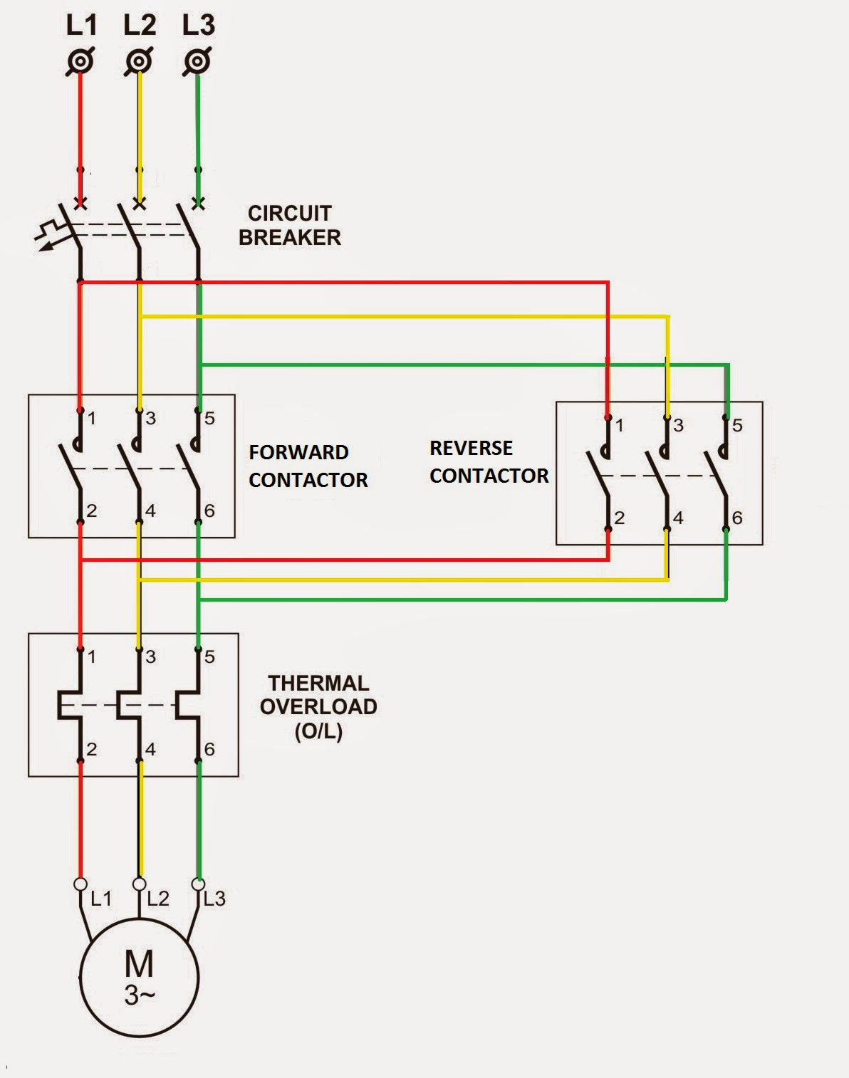
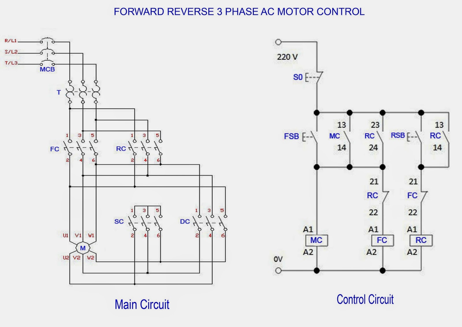
The basic premise of a motor control circuit diagram is to visually represent the connections between the various components involved in controlling a motor. These components typically include the motor itself, a power source, switches, relays, fuses, and overload protection devices. The diagram serves as a blueprint for building and troubleshooting the circuit, ensuring that everything is wired correctly and functions as intended.
The history of motor control circuits is intertwined with the development of electric motors themselves. As motors became more sophisticated, so did the need for more complex control systems. Early motor control circuits were relatively simple, often involving just a switch and a few wires. However, with the advent of solid-state electronics, motor control circuits have evolved into highly sophisticated systems capable of precise control and automation.
Today, the importance of understanding motor control circuit diagrams cannot be overstated. These diagrams are essential for electricians, technicians, engineers, and anyone working with automated systems. They are crucial for troubleshooting malfunctions, designing new systems, and ensuring the safety and efficiency of existing ones. A poorly designed or implemented motor control circuit can lead to equipment damage, safety hazards, and costly downtime.
A simple example of a motor control circuit is a basic start-stop circuit, using a contactor controlled by two push buttons. Pressing the start button energizes the contactor, closing its contacts and completing the circuit to the motor. The contactor maintains its own energized state through an auxiliary contact until the stop button is pressed, breaking the circuit and stopping the motor. This basic concept can be expanded upon to incorporate features like reversing, speed control, and overload protection.
One of the key benefits of a well-designed motor control circuit is enhanced safety. These circuits incorporate protective devices like fuses and overload relays that prevent damage to the motor and other components in the event of a fault. They can also be designed to prevent accidental starts and ensure that the motor operates within safe parameters.
Another benefit is increased efficiency. Modern motor control circuits can optimize motor performance by adjusting speed and torque based on the application's needs. This reduces energy consumption and extends the lifespan of the motor. For example, Variable Frequency Drives (VFDs) allow precise speed control, leading to significant energy savings in applications like pumps and fans.
Finally, motor control circuits enable automation. By integrating with programmable logic controllers (PLCs) and other control systems, they allow for complex automated sequences and processes. This is essential in industrial settings where repetitive tasks and precise control are critical.
A simple action plan for designing a motor control circuit might involve defining the motor's requirements (voltage, current, speed, etc.), selecting appropriate components, creating a wiring diagram, testing the circuit, and implementing safety measures.
Advantages and Disadvantages of Motor Control Circuits
| Advantages | Disadvantages |
|---|---|
| Enhanced Safety | Complexity in Design |
| Increased Efficiency | Cost of Implementation |
| Automation Capabilities | Troubleshooting can be challenging |
Best Practices:
1. Always follow relevant electrical codes and standards.
2. Use appropriate wire sizes and insulation for the current and voltage.
3. Incorporate proper grounding and overcurrent protection.
4. Label all components and wires clearly.
5. Thoroughly test the circuit before putting it into operation.
FAQs:
1. What is the purpose of a motor control circuit? (To control the operation of a motor)
2. What are the basic components of a motor control circuit? (Motor, power source, switches, relays, fuses)
3. How do I read a motor control circuit wiring diagram? (By understanding the symbols and connections)
4. What are some common troubleshooting techniques? (Checking for loose connections, faulty components, etc.)
5. What safety precautions should I take when working with motor control circuits? (Lockout/tagout procedures, proper grounding)
6. What are the different types of motor control circuits? (Direct online starters, star-delta starters, VFDs)
7. How do I choose the right components for my motor control circuit? (Based on the motor's specifications and application requirements)
8. Where can I find more information on motor control circuits? (Textbooks, online resources, industry publications)
In conclusion, motor control circuit wiring diagrams are fundamental to the operation of countless devices and systems we rely on daily. From industrial automation to household appliances, understanding these diagrams is vital for ensuring safe, efficient, and reliable operation. By grasping the principles behind motor control circuits, we can unlock the full potential of electric motors and drive innovation in a wide range of applications. Learning about and working with these circuits can be complex, but the rewards are immense. The ability to control and automate motion is a powerful tool, enabling us to create sophisticated machines and systems that improve our lives in countless ways. Continue learning and exploring the fascinating world of motor control circuits – the future of automation awaits.
Stay ahead of the game uswnt schedule insights
Exploring corvallis oregon a pacific northwest gem
Detroit lions thanksgiving day hat a gridiron tradition


