Unlocking Circuit Secrets: Mastering Electrical Symbols in Schematics

Imagine trying to assemble a complex piece of furniture without instructions. Frustrating, right? Similarly, electrical schematics serve as the instruction manual for electrical circuits. Understanding electrical schematic symbols is essential for anyone working with electronics, from hobbyists to seasoned engineers. These symbols are the language of circuits, providing a visual representation of components and their interconnections.
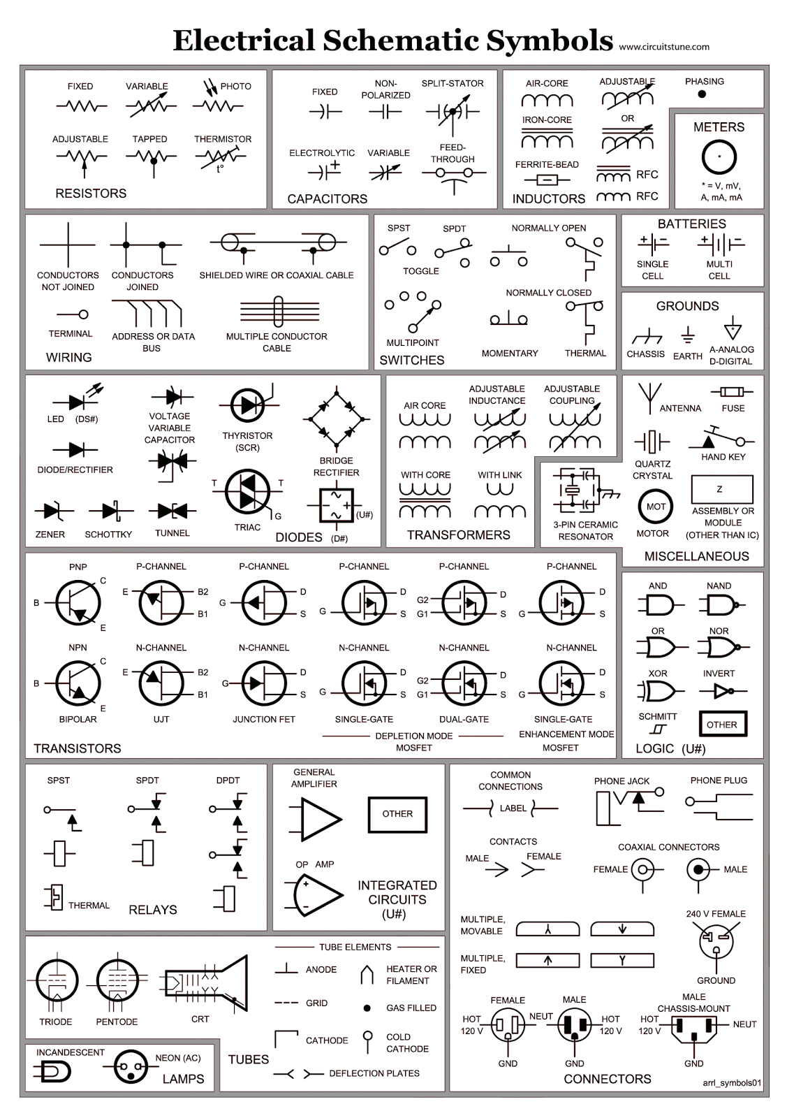
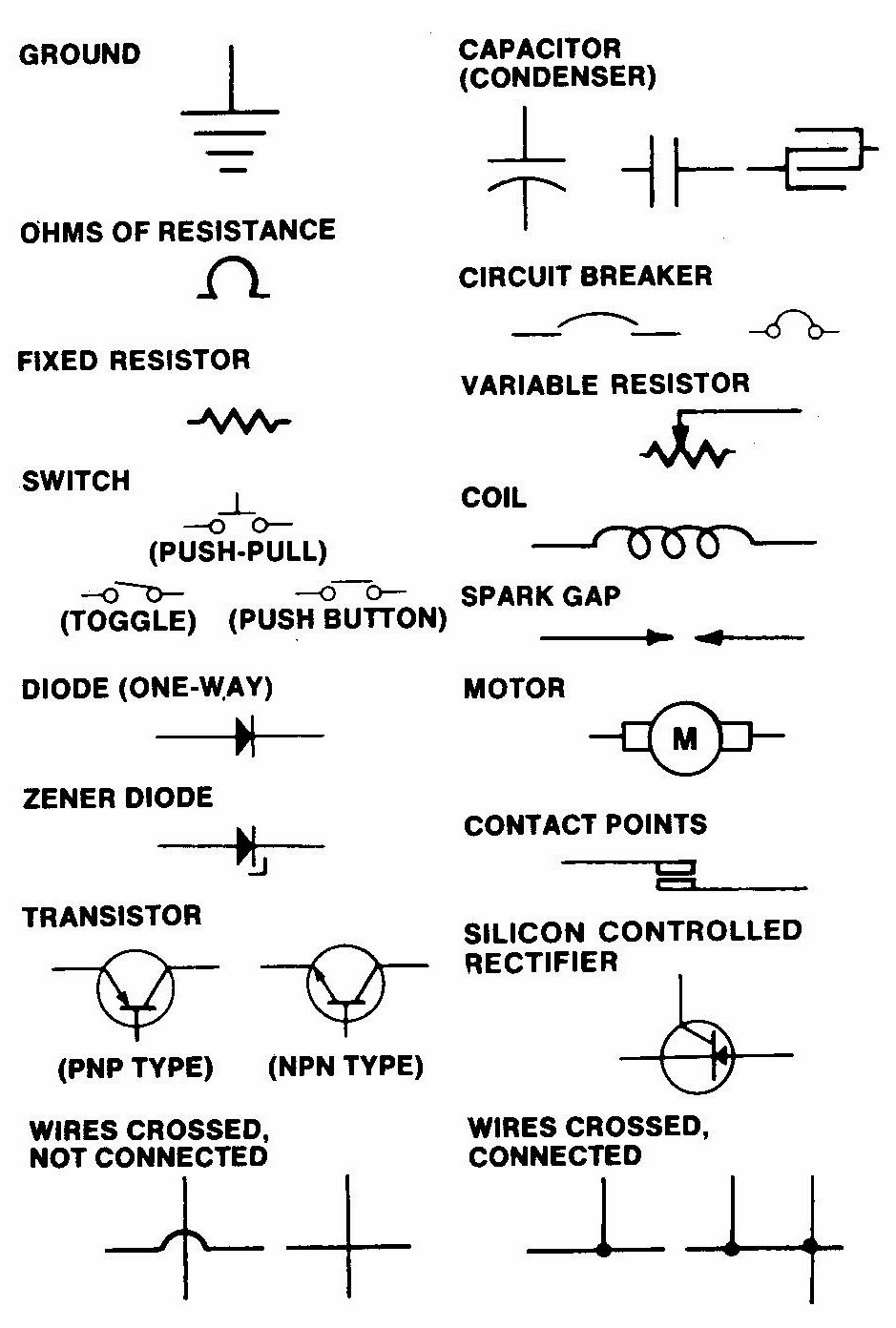
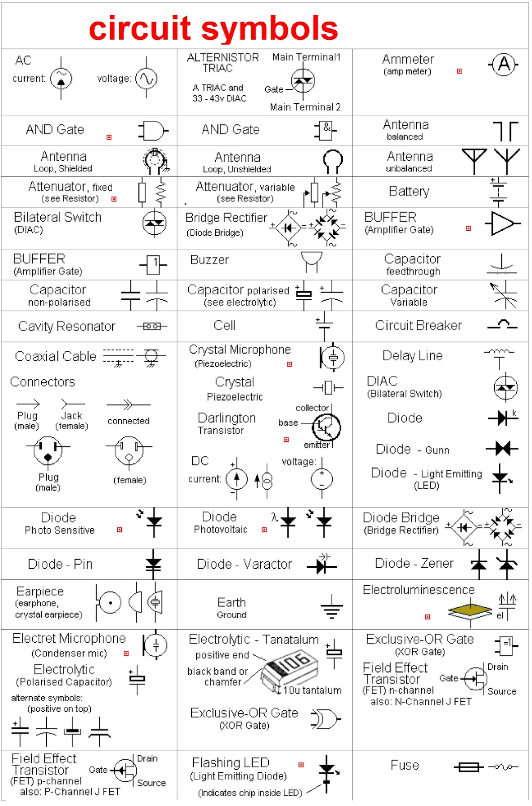
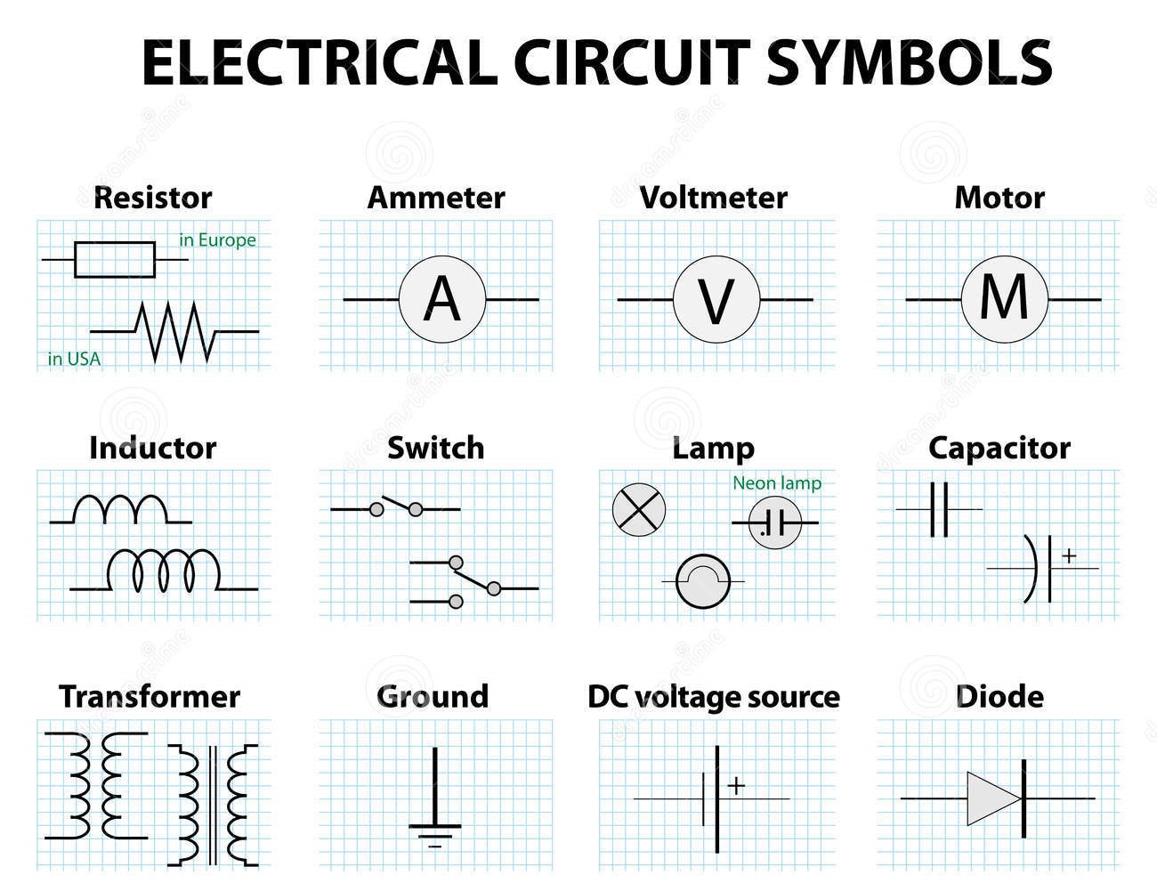
Electrical schematic symbols are standardized graphical representations of electrical and electronic components used in circuit diagrams. They allow engineers and technicians to communicate circuit designs clearly and concisely. Without these symbols, deciphering complex circuits would be a daunting task, prone to misinterpretations and errors. Mastering this symbolic language opens the door to designing, analyzing, and troubleshooting electrical systems effectively.
The history of electrical symbols can be traced back to the early days of electrical experimentation. As the field progressed, the need for a standardized system of representation became apparent. Early symbols were often crude drawings or adaptations of existing symbols from other fields. Over time, organizations like the Institute of Electrical and Electronics Engineers (IEEE) and the International Electrotechnical Commission (IEC) developed standardized sets of symbols to ensure clarity and consistency across the globe.
The importance of using standardized electrical symbols in schematics cannot be overstated. They provide a universal language, facilitating communication and collaboration among engineers worldwide. Imagine the chaos if every engineer used their own unique set of symbols! Standardization prevents ambiguity, reduces errors, and ensures that circuits can be understood and replicated accurately, regardless of who created the schematic.
One of the main issues related to electrical symbols in schematics is keeping up with the constantly evolving technology. New components and technologies emerge regularly, requiring the development of new symbols to represent them. Ensuring that these new symbols are standardized and widely adopted is an ongoing process that involves collaboration between standardization bodies and the industry as a whole.
A resistor, represented by a zig-zag line, limits the flow of current. A capacitor, depicted by two parallel lines, stores electrical energy. A diode, shown as a triangle with a line across one end, allows current to flow in only one direction. These are just a few examples of the numerous symbols used in electrical schematics.
Benefits of using schematic symbols: 1. Clarity and conciseness in representing complex circuits. 2. Universal understanding, enabling engineers worldwide to collaborate effectively. 3. Reduced errors and misinterpretations due to standardization.
Advantages and Disadvantages of Electrical Symbols
| Advantages | Disadvantages |
|---|---|
| Universal understanding | Requires learning and memorization |
| Clear and concise representation | Can become complex for very large circuits |
| Facilitates efficient circuit design and analysis | Constant updates required with new technologies |
Best Practices: 1. Use standardized symbols according to IEC or IEEE standards. 2. Clearly label all components and connections. 3. Maintain consistency in symbol size and orientation. 4. Use a clear and logical layout for the schematic. 5. Document any non-standard symbols used.
Real Examples: 1. Power supply circuits. 2. Amplifier circuits. 3. Control circuits. 4. Logic circuits. 5. Communication circuits.
Challenges and Solutions: 1. Keeping up with new symbols - Solution: Refer to latest standards and industry publications. 2. Complex circuits - Solution: Use hierarchical design and modular schematics. 3. Software compatibility - Solution: Use standardized software formats.
FAQs: 1. What is the symbol for a resistor? 2. What is the symbol for a capacitor? 3. What is the symbol for a diode? 4. What are the main standards for electrical symbols? 5. Where can I find resources for learning electrical symbols?
Tips and Tricks: Familiarize yourself with common symbols. Use online resources and software tools for symbol libraries.
In conclusion, electrical symbols in schematics are indispensable tools for anyone working with electronics. They provide a universal language for describing and analyzing circuits, enabling effective communication and collaboration among engineers worldwide. From the simplest resistor to the most complex integrated circuit, understanding these symbols is crucial for designing, building, and troubleshooting electrical systems. Mastering these symbols not only unlocks the ability to read circuit diagrams but also empowers individuals to create their own electronic innovations. Embracing this visual language is a fundamental step towards proficiency in the exciting world of electronics. Continuously learning and adapting to new symbols and standards will ensure your success in this ever-evolving field. Start exploring the world of electrical symbols today and unlock the power of circuit design.
The intriguing dynamic of henry and william in five nights at freddys
Unlocking the secrets of home health care costs with medicare
Obsessed much decoding the benjamin moore color quest


