Understanding Normally Closed Relay Wiring

Imagine a gate, usually closed, swinging open only when you press a button. That's the essence of a normally closed (NC) relay. This article explores the world of NC relay wiring, simplifying the process for both beginners and those seeking a refresher.
Relays act as electrical switches controlled by a separate, smaller current. Think of them as intermediaries. A small signal can activate the relay, switching a much larger current on or off. In the case of a normally closed relay, the "gate" is the circuit, which is closed by default. Applying a control signal opens the circuit, breaking the flow.
Understanding this fundamental difference between normally open and normally closed relays is crucial. Miswiring can lead to unexpected behavior, potentially damaging equipment. We'll delve into the specific wiring requirements of NC relays shortly, providing clear steps to ensure correct implementation.
The concept of relay control has been around for over a century, evolving from telegraph systems to complex automation. The ability to control high-power circuits with low-power signals is essential in countless applications. NC relays play a vital role in safety systems, where a power interruption should trigger an action, such as activating an alarm or shutting down machinery.
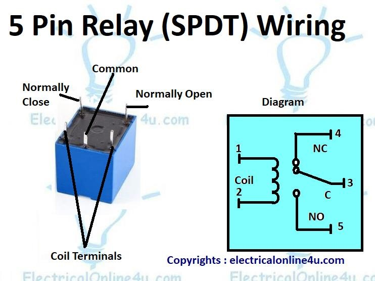
A common challenge in NC relay wiring involves properly identifying the terminals. Relays typically have multiple pins, each with a specific function. Misinterpreting the NC, common (C), and normally open (NO) terminals can lead to incorrect circuit behavior. This article will clarify these designations and offer guidance on identifying them on your specific relay.
Connecting a normally closed relay involves wiring the component you want to control to the NC and C terminals of the relay. The control signal is then applied to the relay coil. When the coil is energized, the connection between NC and C is broken, interrupting the controlled circuit.
Benefits of using NC relays include creating safety mechanisms (e.g., alarm activation upon power failure), enabling remote control of high-power circuits, and simplifying complex control logic. For instance, in a security system, an NC relay can ensure that an alarm activates if the power supply is cut.
Step-by-step guide to wiring a normally closed relay:
1. Identify the terminals: Locate the NC, C, and coil terminals on your relay.
2. Wire the controlled circuit: Connect one side of the controlled circuit to the NC terminal and the other side to the C terminal.
3. Wire the control circuit: Connect the positive side of your control voltage to one side of the relay coil.
4. Connect the ground: Connect the other side of the relay coil to the ground of your control circuit.
Advantages and Disadvantages of NC Relay Wiring
| Advantages | Disadvantages |
|---|---|
| Enhanced Safety Features | Potential for Increased Complexity |
| Simplified Control Logic in Specific Applications | Requires Understanding of NC Relay Behavior |
Best Practices
1. Choose the correct relay for your voltage and current requirements.
2. Use a diode across the relay coil to suppress voltage spikes.
3. Double-check your wiring before applying power.
4. Use appropriate wire gauge for the current being switched.
5. Enclose the relay in a suitable enclosure to protect it from environmental factors.
FAQ
1. What is the difference between NO and NC relays? A normally open (NO) relay completes the circuit when energized, while an NC relay breaks the circuit when energized.
2. How do I choose the right relay? Consider the voltage and current requirements of both the control and controlled circuits.
3. What is the purpose of a diode across the relay coil? It suppresses back EMF, protecting your control circuit.
4. Can I use an NC relay with AC voltage? Yes, but ensure the relay is rated for AC voltage.
5. How do I test a relay? You can use a multimeter to check the continuity between the terminals.
6. What are common issues with NC relay wiring? Incorrect terminal identification, loose connections, and using the wrong relay.
7. How do I troubleshoot a relay circuit? Check the power supply, wiring, and the relay itself using a multimeter.
8. Where can I find more information on relay wiring? Online tutorials, datasheets, and electronics textbooks.
Understanding how to correctly wire a normally closed relay opens up a world of possibilities for controlling electrical circuits. From simple safety mechanisms to complex automation systems, NC relays provide a powerful and versatile tool. Mastering the fundamentals of NC relay behavior, terminal identification, and wiring best practices ensures safe and effective implementation in your projects. By following the steps outlined in this guide and paying close attention to the nuances of NC relay characteristics, you can confidently integrate these components into your electrical designs, benefiting from their unique capabilities in a wide range of applications.
The allure of smoking characters in anime
Navigating bereavement leave compassionately and effectively
Elevate your kitchen with benjamin moore vintage vogue cabinets


