Decoding the Secret Language of Circuits

Ever feel like you're staring at hieroglyphics when you look at an electrical diagram? Don't worry, you're not alone. Those mysterious squiggles, lines, and circles are actually electrical circuit schematic symbols, a universal language that describes the components and connections within an electrical circuit. Understanding these symbols is like unlocking a secret code, giving you the power to navigate the world of electronics.
Imagine trying to describe a complex outfit without using any fashion terminology. It would be a mess, right? Similarly, electrical circuit schematic symbols provide a concise and standardized way to represent circuit elements, avoiding lengthy written descriptions. These symbols act as visual shorthand, allowing engineers and hobbyists alike to communicate circuit designs effectively. They're the foundation of any electrical project, from simple LED circuits to complex computer motherboards.
The journey of electrical circuit schematic symbols began with the rise of electricity itself. As scientists and inventors experimented with electrical currents and devices, the need for a standardized visual representation became apparent. Over time, specific symbols evolved to represent common components like resistors, capacitors, and switches. These symbols have been refined and standardized by organizations like the IEEE (Institute of Electrical and Electronics Engineers), ensuring consistency and clarity across the globe.
The importance of electrical circuit schematic symbols cannot be overstated. They're the blueprints of electrical systems, enabling engineers to design, analyze, and troubleshoot circuits with precision. Without these standardized representations, the world of electronics would be a chaotic jumble of wires and components, making collaboration and innovation nearly impossible.
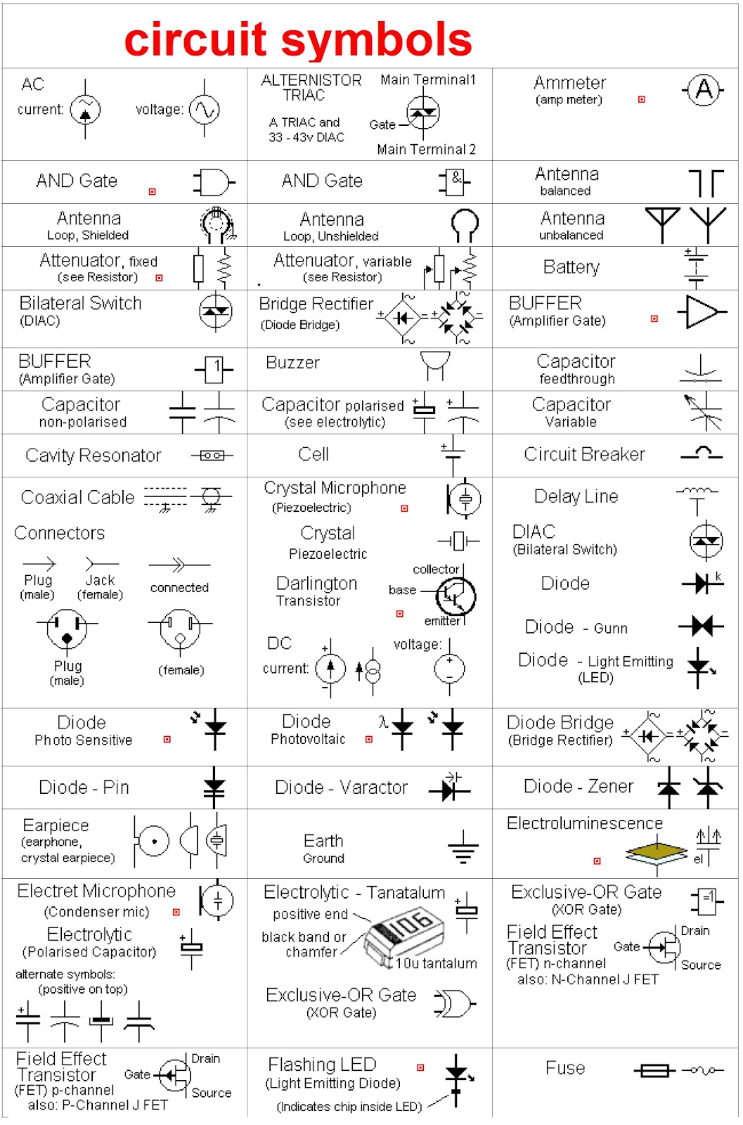
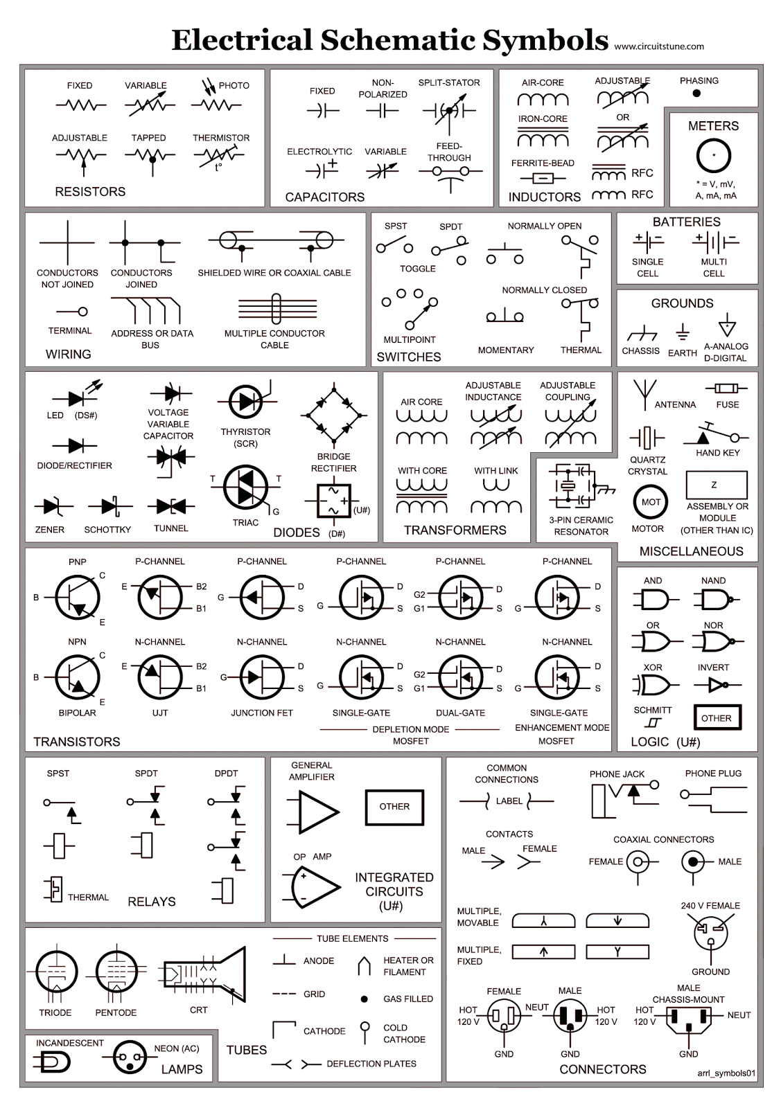
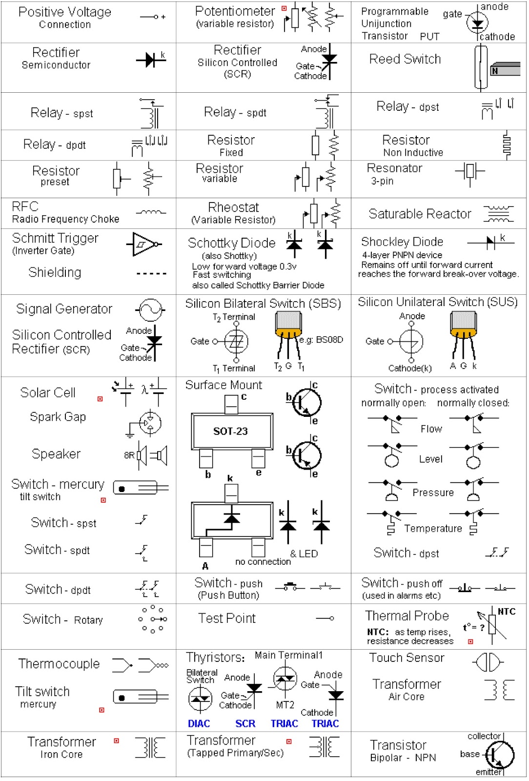
One of the main issues related to electrical circuit schematic symbols is the sheer number of them! It can feel overwhelming at first, like trying to memorize a whole new alphabet. However, just like learning any language, it's about starting with the basics and gradually expanding your vocabulary. Focus on the most common symbols first, and you'll find that the rest become easier to understand as you go along.
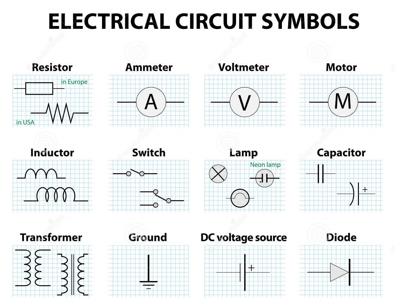
A resistor, represented by a zigzag line, limits the flow of current. A capacitor, symbolized by two parallel lines, stores electrical charge. A switch, depicted as a break in a line with a connecting element, controls the flow of current. These simple examples demonstrate how symbols visually represent the function of each component.
Understanding circuit symbols allows for efficient circuit analysis, streamlined troubleshooting, and effective communication among electrical professionals.
An action plan for mastering circuit symbols involves starting with basic components, practicing reading simple diagrams, and gradually tackling more complex circuits. Online resources and textbooks provide ample practice materials.
Beginners can benefit from a checklist of common symbols, ensuring they can identify key components when analyzing a diagram.
A step-by-step guide to reading a schematic involves identifying the power source, tracing the flow of current, and understanding the function of each component along the path.
Resources like All About Circuits and Electronics Tutorials offer comprehensive information and diagrams.
Advantages and Disadvantages of Using Electrical Circuit Schematic Symbols
| Advantages | Disadvantages |
|---|---|
| Universal understanding | Initial learning curve |
| Concise representation | Can become complex in large circuits |
| Facilitates analysis and troubleshooting | Requires adherence to standards for clarity |
Best practices for using schematic symbols include adhering to standards, maintaining clarity and organization, and using simulation software to verify designs.
Real-world examples include the schematics for a simple flashlight, a basic amplifier circuit, a power supply unit, a digital clock, and a microcontroller-based system.
Challenges in using schematic symbols can include symbol confusion, complex diagrams, and software compatibility issues. Solutions involve using reference guides, breaking down complex diagrams into smaller sections, and ensuring software compatibility.
FAQs about schematic symbols often cover basic symbol identification, resources for learning, software recommendations, and tips for interpreting complex diagrams.
Tips and tricks for working with schematic symbols include using online symbol libraries, practicing with interactive simulations, and seeking guidance from experienced engineers or hobbyists.
In conclusion, electrical circuit schematic symbols are the essential building blocks of electronic design. They represent a universal language that allows engineers and hobbyists worldwide to communicate and collaborate effectively. While the initial learning curve may seem daunting, mastering these symbols is crucial for anyone working with electronics. From designing a simple circuit to troubleshooting complex systems, understanding schematic symbols unlocks the power to innovate and create in the world of electronics. So, embrace the challenge, dive into the world of circuit symbols, and empower yourself to create your own electrical marvels. Start by exploring online resources, practicing with simple circuits, and connecting with the vibrant community of electronics enthusiasts. The future of electronics awaits, and it speaks the language of schematic symbols.
Texas city on wheels your enterprise rental car adventure
Ash blue hair the ultimate guide to achieving and maintaining this trendy hue
Dead car battery amazons portable jump starters to the rescue


