Decoding the Language of Circuits: Electronics Component Names and Symbols

Ever wondered how electronic devices, from simple calculators to complex smartphones, function flawlessly? The answer lies in the intricate network of electronic components meticulously arranged on circuit boards. Understanding the language of these components—their names and symbols—is crucial for anyone venturing into the world of electronics.
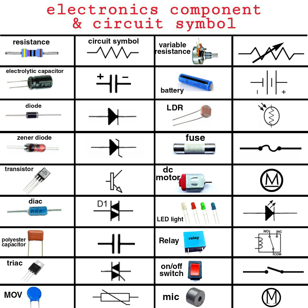
Imagine trying to assemble a puzzle without knowing the shapes of the pieces. Similarly, comprehending electronic circuits requires a grasp of component identification. This involves recognizing both the name of a component, such as a resistor or capacitor, and its corresponding symbol, a simplified graphical representation used in circuit diagrams.
Electronic component designations and symbols form the bedrock of circuit design and analysis. These standardized representations enable engineers and hobbyists worldwide to communicate effectively, ensuring clear and concise circuit diagrams. From basic resistors to sophisticated integrated circuits, each component plays a specific role, and their symbols provide a visual shorthand for understanding their function within a circuit.
The history of electronic component symbolic representation has evolved alongside the advancements in electronics. Initially, rudimentary drawings were employed, but as circuits became more complex, standardized symbols emerged. Organizations like the Institute of Electrical and Electronics Engineers (IEEE) and the International Electrotechnical Commission (IEC) played pivotal roles in establishing universally recognized symbols.
The importance of standardized electronic component identification cannot be overstated. It eliminates ambiguity, facilitates collaboration, and ensures that circuit designs are interpreted consistently across different platforms and by diverse individuals. This standardization is crucial for troubleshooting, manufacturing, and sharing electronic designs.
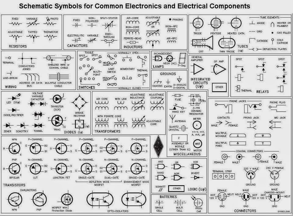
Electronic component names typically reflect their function. For example, a resistor resists the flow of current, a capacitor stores electrical charge, and a diode allows current to flow in only one direction. Each component also has a unique symbol, often resembling its physical appearance or representing its function abstractly.
A simple example is the resistor. Its name indicates its function – resisting current flow. Its symbol, a zigzag line, visually represents the impedance to current. Similarly, a capacitor's symbol, two parallel lines, resembles its structure of two conductive plates separated by an insulator.
One key benefit of understanding component names and symbols is the ability to read and interpret circuit diagrams. This skill is essential for building, repairing, or modifying electronic devices.
Another advantage is effective communication with other electronics enthusiasts or professionals. Using the correct terminology and symbols ensures that everyone is on the same page, avoiding confusion and potential errors.
Furthermore, knowing component identification aids in troubleshooting faulty circuits. By understanding the function and symbol of each component, you can identify potential problem areas more efficiently.
Advantages and Disadvantages of Standardized Component Identification
| Advantages | Disadvantages |
|---|---|
| Clear communication | Initial learning curve |
| Facilitates collaboration | Symbol variations can exist |
| Simplified circuit analysis | Requires ongoing updates with new components |
Best Practices for learning electronic component identification:
1. Start with basic components: Focus on resistors, capacitors, diodes, transistors before moving on to more complex integrated circuits.
2. Utilize online resources: Numerous websites and apps offer interactive tutorials and component databases.
3. Practice reading circuit diagrams: Analyze simple circuits to familiarize yourself with component placement and connections.
4. Build simple circuits: Hands-on experience solidifies understanding and helps connect symbols with real-world components.
5. Join online communities: Engage with fellow electronics enthusiasts to exchange knowledge and seek guidance.
Frequently Asked Questions:
1. What is the symbol for a diode? - A triangle with a line perpendicular to one side.
2. What does a capacitor do? - Stores electrical charge.
3. What is the unit of resistance? - Ohm (Ω).
4. What is an integrated circuit? - A miniature electronic circuit contained within a single chip.
5. Where can I find a comprehensive list of electronic component symbols? - Datasheets and online resources.
6. What are some common types of transistors? - Bipolar junction transistors (BJTs) and field-effect transistors (FETs).
7. How do I identify a component in a physical circuit? - Refer to its markings and compare it with datasheets or online resources.
8. What are some tools used to identify components in circuits? – Multimeters and component testers.
Tips and tricks for mastering component identification include using flashcards, creating your own component library, and regularly practicing circuit analysis. One real world example of component identification’s importance can be seen in repairing a malfunctioning electronic device.
In conclusion, understanding electronics components, their names, and their symbolic representation is paramount in the world of electronics. From simplifying circuit design to facilitating effective communication among engineers, the standardized system of component identification plays a critical role. Mastering these fundamentals unlocks the ability to read circuit diagrams, troubleshoot electronic devices, and even design your own circuits. By investing time in learning this foundational knowledge, you'll embark on a rewarding journey into the fascinating realm of electronics, empowered to explore, create, and innovate. So, start exploring the world of electronic components today, and unlock the power to build the future of technology.
Wrenching wisdom mastering your gmc sierra 1500s lug nut torque
Unlocking your jeeps wheel potential the definitive guide to rim bolt patterns
Finding the best japanese traditional tattoo artists in your area