Decoding Hydraulic Schematics: Symbols, Meanings, and More

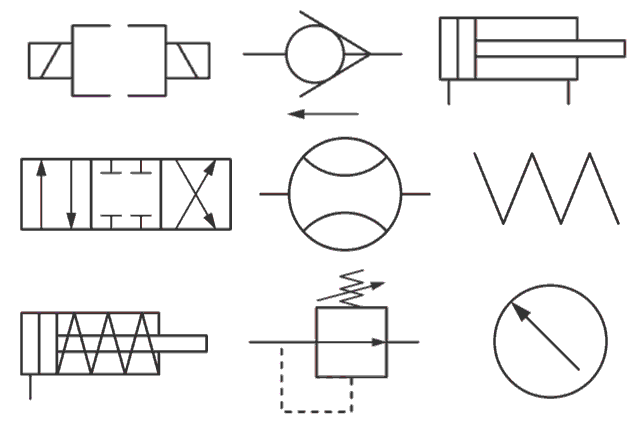
Ever wondered how complex machinery like excavators and cranes operate so smoothly? The secret lies in hydraulic systems, and understanding their blueprints, known as hydraulic schematics, is key. These schematics use a standardized language of symbols to represent various components and their connections. Decoding these hydraulic schematic symbols and their meanings is essential for anyone working with hydraulic systems, from design and maintenance to troubleshooting and repair.
Hydraulic schematics are more than just drawings; they are the roadmap to a hydraulic system's functionality. They visually depict the flow of hydraulic fluid, the interaction of components, and the overall logic of the system's operation. This graphical representation allows technicians and engineers to quickly grasp the system's layout and identify potential issues.
The significance of hydraulic symbol interpretation cannot be overstated. Misinterpreting even a single symbol can lead to costly errors during system design, installation, or maintenance. A thorough understanding of these symbols ensures efficient troubleshooting, prevents downtime, and enhances overall system performance.
These symbols haven't always been standardized. Early hydraulic diagrams often used varied representations, leading to confusion and miscommunication. The adoption of standardized hydraulic schematic symbols has revolutionized the industry, fostering clear communication and facilitating collaboration among professionals worldwide.
The International Organization for Standardization (ISO) plays a crucial role in maintaining these standards. ISO 1219-1 defines the graphical symbols for hydraulic schematics, ensuring consistency across different industries and regions. This standardization allows engineers and technicians to interpret hydraulic diagrams regardless of their origin.
A simple example is the symbol for a hydraulic pump, often depicted as a circle with an arrow indicating the direction of fluid flow. Another common symbol is the hydraulic cylinder, represented by a rectangle with a piston rod. Understanding these basic symbols forms the foundation for interpreting more complex hydraulic diagrams.
One of the primary benefits of standardized hydraulic schematic symbols is improved communication. Engineers and technicians can effectively share information and collaborate on projects, even if they speak different languages. This clear communication minimizes errors and ensures efficient teamwork.
Another significant advantage is enhanced troubleshooting. By quickly identifying components and their connections within the schematic, technicians can pinpoint the root cause of system malfunctions and implement effective solutions. This streamlines the repair process and reduces downtime.
Furthermore, standardized hydraulic schematic symbols contribute to better system design. Engineers can easily visualize the layout and optimize the placement of components, resulting in improved efficiency and performance of the hydraulic system.
As a starting point, familiarize yourself with ISO 1219-1. This standard provides a comprehensive overview of hydraulic schematic symbols. Supplement this knowledge with practical experience by analyzing real-world hydraulic schematics and relating the symbols to their corresponding components in physical systems.
Advantages and Disadvantages of Standardized Hydraulic Schematic Symbols
| Advantages | Disadvantages |
|---|---|
| Clear Communication | Requires Initial Learning |
| Efficient Troubleshooting | Potential for Misinterpretation if not properly understood |
| Improved System Design | Constant Updates to Standards Require Ongoing Learning |
Best Practice 1: Adhere to ISO Standards
Best Practice 2: Use Clear and Concise Labels
Best Practice 3: Maintain Consistent Symbol Orientation
Best Practice 4: Use a Logical Layout
Best Practice 5: Regularly Review and Update Schematics
Example 1: Hydraulic System of an Excavator
Example 2: Hydraulic System of a Crane
Example 3: Hydraulic System of a Forklift
Example 4: Hydraulic System of an Airplane Landing Gear
Example 5: Hydraulic System of a Press Machine
Challenge 1: Keeping Up with Standard Updates. Solution: Regular Training
Challenge 2: Complex Systems. Solution: Breaking Down the System into Smaller Circuits
Challenge 3: Software Compatibility. Solution: Utilizing Industry-Standard Software
Challenge 4: Legacy Schematics. Solution: Gradual Conversion to Modern Standards
Challenge 5: Inconsistent Symbol Usage. Solution: Implementing Strict Adherence to ISO Standards.
FAQ 1: What is the symbol for a hydraulic pump?
FAQ 2: What is the symbol for a hydraulic valve?
FAQ 3: What is the symbol for a hydraulic cylinder?
FAQ 4: What is the symbol for a hydraulic motor?
FAQ 5: What is the symbol for a hydraulic filter?
FAQ 6: What is the symbol for a hydraulic accumulator?
FAQ 7: What is the symbol for a hydraulic pressure gauge?
FAQ 8: Where can I find a complete list of hydraulic schematic symbols?
Tips and Tricks: Use software tools for creating and editing hydraulic schematics. Cross-reference symbols with component datasheets for accurate representation. Participate in industry forums and workshops to stay updated on the latest standards and best practices.
In conclusion, understanding hydraulic schematic symbols and meaning is paramount for anyone involved in the design, installation, maintenance, and repair of hydraulic systems. These symbols form the universal language of hydraulics, enabling clear communication, efficient troubleshooting, and optimized system design. By mastering this language, you unlock the power to effectively interpret complex hydraulic systems and ensure their optimal performance. The benefits of standardized symbols are clear: reduced errors, enhanced safety, and improved efficiency. Continuous learning and adherence to ISO standards are essential for staying proficient in the ever-evolving field of hydraulics. Embrace the power of hydraulic schematics, and unlock the potential of fluid power technology.
Taming the yaml beast your guide to snakeyaml in maven
Madden 25 team creation guide
Navigating medicare supplement plans find local providers


