Decoding Circuit Whispers Electronic Schematic Symbols Unveiled

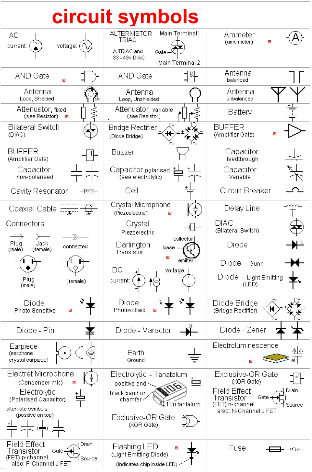
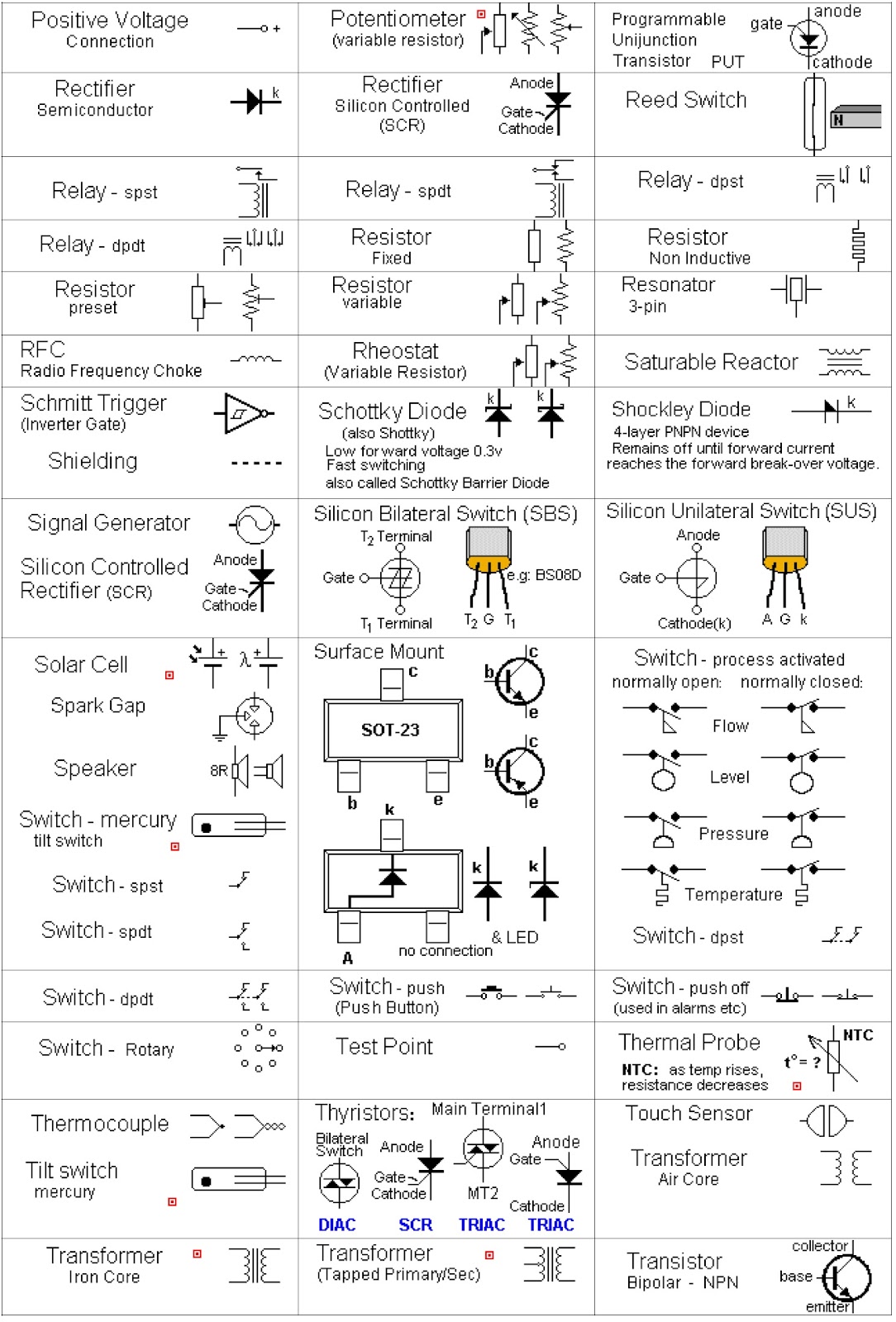
Ever wondered how engineers communicate the intricate language of electronics? The answer lies in the universal lexicon of electronic schematic symbols. These visual representations are the building blocks of circuit diagrams, providing a concise and standardized way to depict electronic components and their interconnections. Mastering these symbols is crucial for anyone venturing into the world of electronics, from hobbyists tinkering with Arduino projects to seasoned engineers designing complex integrated circuits.
Electronic schematic diagrams are essentially the blueprints of electronic circuits. Imagine trying to build a house without a blueprint – chaos, right? Similarly, electronic schematic symbols provide the roadmap for assembling electronic components, ensuring proper functionality and avoiding costly errors. Without a standardized set of symbols, the world of electronics would be a confusing jumble of proprietary representations, hindering collaboration and innovation.
The history of schematic symbols is intertwined with the development of electronics itself. Early diagrams often relied on pictorial representations of components, evolving over time into the abstract symbols we use today. Standardization efforts by organizations like the IEEE (Institute of Electrical and Electronics Engineers) and IEC (International Electrotechnical Commission) have been instrumental in creating a globally recognized system, fostering clear communication and interoperability within the electronics industry.
Understanding electronic diagrams is paramount for troubleshooting, repairing, and designing electronic circuits. These visual representations provide a clear and concise way to analyze circuit behavior, identify faulty components, and predict performance. From simple resistor networks to complex microcontroller circuits, the ability to interpret schematic symbols is a fundamental skill for any electronics enthusiast or professional. Misinterpreting a symbol can lead to incorrect circuit assembly, malfunctioning devices, and even safety hazards.
Common issues related to understanding electronic blueprints include confusion between similar-looking symbols, difficulty interpreting complex diagrams with numerous components, and keeping up with evolving symbol standards. Resources like online symbol libraries, textbooks, and software tools can greatly assist in overcoming these challenges. Learning to read these diagrams is like learning a new language – it requires practice, patience, and a willingness to explore the nuances of electronic communication.
For example, a resistor is represented by a zigzag line, a capacitor by two parallel lines, and a diode by a triangle pointing towards a line. These simple symbols convey a wealth of information about the component's function and characteristics. Understanding these symbols allows engineers to quickly grasp the overall circuit architecture and analyze its behavior.
Benefits of using standardized electrical symbols include clear communication, efficient troubleshooting, and streamlined design processes. For example, a team of engineers working on a collaborative project can easily share and interpret circuit diagrams regardless of their geographical location or native language. Standardized representation ensures everyone is on the same page, minimizing miscommunication and errors.
Beginners can start by learning basic component symbols and gradually progress to more complex circuits. Online tutorials, interactive simulators, and hands-on projects can provide a valuable learning experience. Building simple circuits based on schematic diagrams is an excellent way to solidify understanding and gain practical experience.
Advantages and Disadvantages of Standardized Electronic Schematic Symbols
| Advantages | Disadvantages |
|---|---|
| Clear and concise communication | Can be overwhelming for beginners |
| Facilitates troubleshooting and repair | Requires ongoing learning to stay updated with new symbols |
| Streamlines design process | Potential for misinterpretation if not carefully studied |
Best practices for using symbols include adhering to established standards, using clear and consistent labeling, and organizing diagrams logically. Software tools can automate many aspects of schematic creation, ensuring accuracy and consistency. Regularly reviewing and updating symbol libraries is crucial for staying current with industry standards and best practices.
Frequently asked questions include: What is the symbol for a transistor? What is the difference between a capacitor and a resistor symbol? Where can I find a comprehensive electronic symbol chart? These questions highlight the importance of readily available resources and continuous learning in the field of electronics.
Tips for mastering these visual representations of components include practicing reading diagrams regularly, utilizing online symbol libraries, and engaging in hands-on projects. Building circuits based on schematic diagrams is an excellent way to reinforce understanding and gain practical experience.
In conclusion, electronic schematic symbols are the essential language of circuit design, enabling clear communication, efficient troubleshooting, and streamlined development. From simple resistors to complex integrated circuits, these symbols form the foundation of electronic innovation. Mastering this visual language is crucial for anyone involved in the world of electronics, empowering them to design, analyze, and build the circuits that power our modern world. Continuous learning, utilizing available resources, and actively engaging with schematic diagrams will unlock the full potential of this powerful tool, enabling individuals to contribute to the ever-evolving landscape of electronics. Embracing this symbolic language is not just about understanding circuits; it's about unlocking the potential of innovation and shaping the future of technology. Start your journey today and explore the fascinating world of electronic schematic symbols!
Decoding the optum rx fax form labyrinth
Ann arbors greatest games exploring the top gaming experiences
Unlocking the vibrancy exploring the world of flamingo feathers


