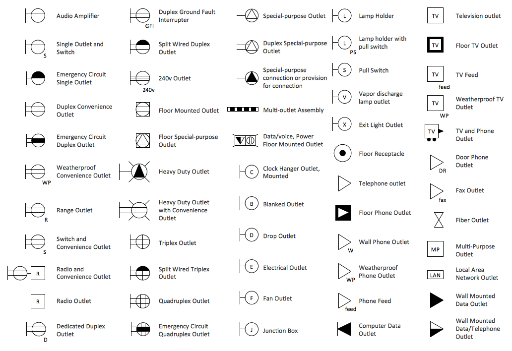
Decoding Building Plans Electrical Symbols

Ever wondered what those squiggles and circles on building blueprints mean? They're not just random doodles; they're a crucial language for electricians, architects, and anyone involved in construction. We're talking about electrical symbols for building plans, a system of graphic representations that detail the electrical layout of a structure. These symbols represent everything from light switches and outlets to complex wiring systems, forming the backbone of safe and efficient electrical installations.
Understanding these symbols is like having a secret decoder ring for construction projects. Imagine trying to build a house without knowing where the lights should go or how the power gets to the kitchen appliances. That’s where electrical diagrams with their standardized symbols step in, preventing miscommunication and ensuring everyone is on the same page, literally.
The history of electrical symbols is intertwined with the development of electricity itself. As electrical systems became more complex, the need for a standardized visual language arose. Early representations were often crude and varied, leading to confusion and errors. Over time, organizations like the National Electrical Manufacturers Association (NEMA) and the International Electrotechnical Commission (IEC) worked to standardize these symbols, creating a universal lexicon for the electrical trade.
These standardized electrical drawing symbols are vital for several reasons. Primarily, they provide a clear and concise way to communicate complex electrical designs. This avoids ambiguity, minimizes errors during installation, and ensures that the finished product meets safety regulations. These symbols also play a crucial role in troubleshooting and maintenance, enabling electricians to quickly identify and address electrical issues.
One common issue with electrical symbols is the potential for variations or outdated symbols on older plans. This highlights the importance of referencing current standards and ensuring that everyone involved in a project is using the same set of symbols. Misinterpreting a symbol could lead to costly mistakes and safety hazards.
For example, a simple "S" within a circle represents a single-pole switch. A duplex receptacle, commonly known as a standard electrical outlet, is depicted by two vertical lines connected by a short horizontal line. Understanding these symbols allows electricians to accurately install the correct components in the designated locations.
One key benefit of using electrical symbols is improved communication. They provide a universal language understood by all professionals involved in a construction project. This reduces the risk of misunderstandings and errors, saving both time and money.
Another advantage is enhanced safety. By clearly illustrating the electrical layout, including safety features like ground fault circuit interrupters (GFCIs), these symbols contribute to a safer working environment and minimize the risk of electrical hazards.
Finally, the use of electrical symbols facilitates efficient troubleshooting and maintenance. They allow electricians to quickly identify and diagnose electrical problems, streamlining the repair process and reducing downtime.
To effectively implement electrical symbols, create a detailed electrical plan, reference the latest standards, clearly label all symbols, use a legend, and review the plan thoroughly before starting any electrical work.
Advantages and Disadvantages of Standardized Electrical Symbols
| Advantages | Disadvantages |
|---|---|
| Clear Communication | Potential for Misinterpretation if Outdated Symbols are Used |
| Enhanced Safety | Requires Training and Familiarity with Standards |
| Efficient Troubleshooting | Variations in Regional or International Standards |
Five real-world examples of electrical symbols include those for switches, outlets, lights, circuit breakers, and grounding wires. Each symbol provides specific information about the type and function of the electrical component.
A common challenge is keeping up with evolving standards. The solution is to regularly consult updated resources and participate in continuing education programs.
Frequently Asked Questions: What do electrical symbols represent? Where can I find a comprehensive list of electrical symbols? Why are these symbols important? What are the common symbols for switches and outlets? How are these symbols used in building plans? What are GFCI symbols? What are the symbols for different types of wiring? How do I interpret electrical diagrams?
A helpful tip is to keep a laminated chart of common electrical symbols handy for quick reference.
In conclusion, understanding electrical symbols for building plans is essential for anyone involved in the construction industry. From facilitating clear communication to ensuring safety and efficiency, these symbols play a critical role in bringing electrical designs to life. By learning and utilizing these symbols correctly, we can build safer, more efficient, and more reliable electrical systems. Familiarizing yourself with these symbols is an investment in your professional development and a commitment to best practices in the electrical field. Whether you're an experienced electrician, an aspiring architect, or a homeowner embarking on a renovation project, mastering the language of electrical symbols empowers you to navigate the complexities of building plans with confidence and contribute to successful construction outcomes. Explore the resources available, stay updated with the latest standards, and embrace the power of clear communication through the universal language of electrical symbols.
Unlocking global futures beijing foreign studies university and lin shen
Unlocking the pitch ea fc 24 new player cards
Understanding your motorcycles starter relay a comprehensive guide


