Decode Your Circuits: Mastering Electrical Diagram Symbols

Ever stared at a circuit diagram and felt like you were deciphering hieroglyphics? Electrical circuits, the backbone of our modern world, are represented by a language of symbols, a shorthand that allows engineers and hobbyists alike to communicate complex designs. Understanding these electrical symbol representations is crucial for anyone working with electronics, whether you’re troubleshooting a faulty appliance or designing the next groundbreaking gadget.
So, what exactly are these symbols, and why are they so important? They're graphical representations of electrical components, acting as a universal language in the world of electronics. Think of them as the words and punctuation marks of circuit diagrams, each carrying a specific meaning that contributes to the overall message of the design. Mastering these symbols is the key to unlocking the secrets held within these diagrams.
The history of electrical symbols is intertwined with the development of electricity itself. As scientists and engineers began experimenting with electrical phenomena, the need for a standardized way to represent their work became apparent. Early diagrams were often crude, using simple shapes to depict basic components. Over time, these evolved into the more standardized symbols we use today, driven by the need for clear communication and international collaboration in electrical engineering projects.
The importance of standardized electrical circuit symbols cannot be overstated. They provide a concise and universally understood way to represent complex electrical systems. This standardization is essential for effective communication between engineers, technicians, and hobbyists, preventing misinterpretations that could lead to costly mistakes or even dangerous situations. Imagine the chaos if every engineer used their own unique set of symbols – it would be like trying to read a book written in a different language on every page.
One of the main issues surrounding electric circuit symbols is keeping up with the constant advancements in technology. New components are continuously being developed, each requiring a new symbol to represent its function within a circuit. Organizations like the IEEE (Institute of Electrical and Electronics Engineers) play a vital role in standardizing these new symbols, ensuring that the language of circuit diagrams remains consistent and comprehensible across the globe.
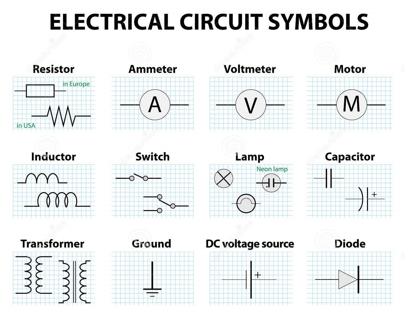
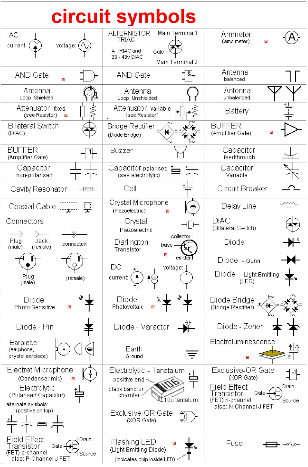
Let's consider a simple example: the resistor. Its symbol is a zigzag line, representing its function of impeding the flow of current. A capacitor, which stores electrical energy, is represented by two parallel lines. These symbols, along with many others, form the building blocks of circuit diagrams, allowing us to visualize the flow of electricity and the relationships between components.
One major benefit of using symbols is clarity. They provide a concise representation of complex circuits, making them easier to understand and analyze. Another benefit is universality. These symbols are recognized worldwide, facilitating communication and collaboration between engineers from different backgrounds. Finally, the use of symbols promotes efficiency. They save time and space, allowing engineers to quickly sketch and interpret circuit diagrams without having to write lengthy descriptions of each component.
Advantages and Disadvantages of Standardized Electrical Symbols
| Advantages | Disadvantages |
|---|---|
| Clear Communication | Keeping up with new technology |
| Universal Understanding | Potential for misinterpretation if not learned properly |
| Efficiency in Design |
Best Practice 1: Always refer to a standardized symbol guide when drawing or interpreting circuits.
Best Practice 2: Keep your diagrams neat and organized to avoid confusion.
Best Practice 3: Label all components clearly with their designated values.
Best Practice 4: Use consistent spacing between symbols to improve readability.
Best Practice 5: Double-check your diagrams for errors before implementation.
Example 1: A simple circuit with a battery, resistor, and LED.
Example 2: A more complex circuit with multiple resistors and capacitors.
Example 3: A circuit diagram for a simple power supply.
Example 4: A circuit diagram for an amplifier.
Example 5: A circuit diagram for a timer circuit.
Challenge 1: Remembering the vast number of symbols. Solution: Use flashcards or online resources for practice.
FAQ 1: What is the symbol for a diode? A: A triangle with a line across one end.
In conclusion, electrical circuit symbols are the fundamental language of electronics. They provide a concise, universal, and efficient way to represent complex circuits, enabling effective communication and collaboration amongst engineers worldwide. From the simplest resistor to the most complex integrated circuit, these symbols are essential for anyone working with electronics. Understanding and mastering these graphical representations is not just a helpful skill; it’s the key to unlocking the potential of electrical design and empowering you to create, innovate, and solve problems in the exciting world of electronics. Take the time to study and familiarize yourself with these symbols – it’s an investment that will pay dividends throughout your electronics journey.
Unmasking the academy undercover professor manga phenomenon
Exploring incarceration alternatives a look at prison boot camps
The story behind cody rhodes iconic dark hair


